1. Project Overview
This solution provides a point-to-point single-wavelength 400G coherent transmission system, primarily designed to meet the needs of high-speed, large-capacity data transmission, such as Data Center Interconnects (DCI) and backbone network core links.
By integrating Dense Wavelength Division Multiplexing (DWDM) technology with 400G coherent transceiver technology, and incorporating optical path protection, power amplification, and flexible channel separation, the system enables stable and reliable 400G-level data exchange between Site A and Site B.
In addition, it supports main and backup link redundancy, ensuring uninterrupted service continuity.
2. System Core Configuration List
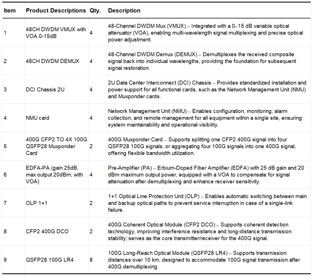
The hardware configuration of this solution is designed around five key functional modules: Mux/Demux, Amplification, Coherent Transmission, Network Management, and Protection.
The detailed product list is as follows:
3. System Design
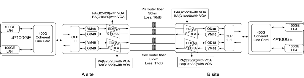
This solution adopts a point-to-point dual-link (main and backup) architecture covering Site A and Site B. The core design revolves around the complete process of signal processing – multiplexing & amplification – link transmission – demultiplexing & restoration – protection & backup, ensuring stable 400G signal transmission over a 30–32 km optical link.
3.1 Link Parameters and Topology
The solution is designed with two independent optical fiber links (main and backup) to accommodate different transmission distances and loss conditions. The specific parameters are as follows:
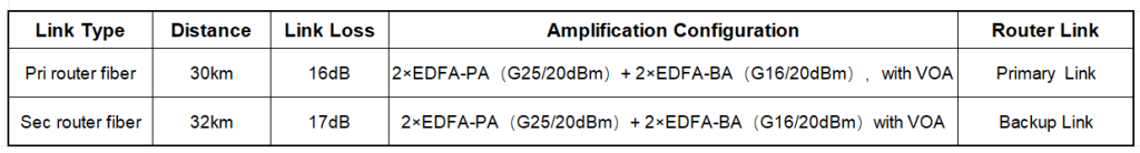
Note: EDFA-BA refers to a Booster Amplifier, with a 16 dB gain and a maximum output power of 20 dBm, used to enhance the transmission power of the multiplexed signal and compensate for long-distance link loss.
The VOA (Variable Optical Attenuator) allows real-time optical power adjustment to prevent transmission errors caused by signal overload or insufficient power.
3.2 Signal Transmission Process (Taking Site A → Site B as an Example)
3.2.1 Signal Generation and Demultiplexing:
At Site A, a 400G coherent signal is generated by the CFP2 400G DCO module. This signal is connected to a 400G CFP2-to-4×100G QSFP28 Muxponder card, which splits the 400G signal into four independent 100G signals.
3.2.2 100G Signal Adaptation:
Each of the four 100G signals is connected to a QSFP28 100G LR4 module, converting electrical signals into optical signals suitable for long-distance transmission.
3.2.3 DWDM Multiplexing:
The four 100G optical signals enter the 48-channel DWDM VMUX, where they are multiplexed into a single DWDM signal (along with other wavelength channels if expansion is needed). The integrated VOA in the VMUX is used to fine-tune optical power to the optimal level.
3.2.4 Signal Amplification:
The multiplexed signal first passes through an EDFA-PA (Pre-Amplifier) to improve receiver sensitivity, and then through an EDFA-BA (Booster Amplifier) to increase output power, effectively compensating for link loss.
3.2.5 Optical Path Protection Switching:
The amplified signal is routed through a 1+1 Optical Line Protection (OLP) unit, which automatically switches between the main and backup links based on link status. Under normal conditions, the 30 km main link is used; in the event of a failure, the system seamlessly switches to the 32 km backup link.
3.2.6 Long-Distance Transmission:
The signal is transmitted from Site A to Site B via the main or backup optical fiber link.
3.2.7 Signal Reception and Restoration:
At Site B, the received signal is amplified again by EDFA-PA + BA to compensate for transmission loss, then demultiplexed by the 48-channel DWDM DEMUX into the original four 100G signals.
Finally, these are recombined into a 400G signal via the 400G Muxponder card and transmitted through the CFP2 400G DCO module to the router at Site B, completing the entire transmission process.
3.3 Core Technical Highlights
3.3.1 400G Coherent Transmission Technology:
Utilizing the CFP2 400G DCO module with coherent detection capability, this technology improves spectral efficiency through phase and polarization multiplexing. It offers stronger interference resistance and maintains a low Bit Error Rate (BER) even over 300+ km transmission links.
3.3.2 1+1 Optical Path Protection (OLP):
The main and backup links are monitored in real time, with automatic failover switching in less than 50 ms, ensuring zero service interruption. This high-reliability design is ideal for financial networks, government data transmission, and other mission-critical applications.
3.3.3 EDFA Multi-Stage Amplification + VOA Adjustment:
A two-stage amplification design (Pre-Amplifier + Booster Amplifier) compensates for 16–17 dB of link loss, while the VOA dynamically adjusts optical power in real time to prevent module damage from excessive power or signal loss due to insufficient power.
3.3.4 Flexible Bandwidth Aggregation and Distribution:
The 400G-to-4×100G Muxponder card supports both “400G aggregation” and “4×100G breakout” modes, enabling flexible connectivity with either 400G core devices or 100G edge equipment, thus adapting to various network application scenarios.
4. Deployment and Link Mapping
4.1 Deployment
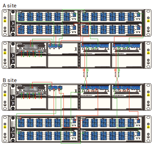
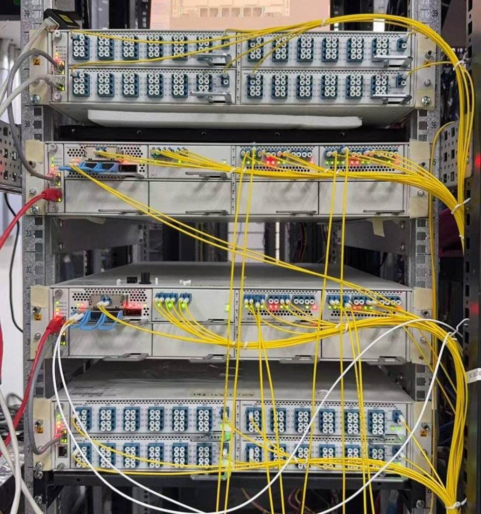
All devices in this solution are deployed in standardized racks, with the following core characteristics:
- Device Integration: The 2U DCI chassis serves as the central platform, housing functional cards such as the NMU card and 400G Muxponder card. The 48-channel DWDM VMUX/DEMUX, EDFA-PA/BA, and 1+1 OLP units are connected to the chassis via standard optical patch cords.
- Module Installation: The CFP2 400G DCO and QSFP28 100G LR4 modules are directly inserted into the Muxponder card or router optical ports, enabling easy installation and maintenance without service interruption during replacement.
- Clear Labeling: In the physical deployment, main/backup link patch cords, device power supplies, and alarm indicators are all clearly labeled, allowing maintenance personnel to quickly locate faults.
4.2 Link Mapping (Site A → Site B)
The link mapping is structured around a three-tier “Site – Device – Link” hierarchy, clearly illustrating signal flow:
- Site A:
Router → CFP2 400G DCO → 400G Muxponder Card → QSFP28 100G LR4 → 48-Channel VMUX → EDFA-PA → EDFA-BA → 1+1 OLP → Main/Backup Optical Fiber Link - Site B:
Main/Backup Optical Fiber Link → 1+1 OLP → EDFA-PA → EDFA-BA → 48-Channel DEMUX → QSFP28 100G LR4 → 400G Muxponder Card → CFP2 400G DCO → Router
5. Solution Advantages Summary
5.1 High-Speed, Large-Capacity:
400G coherent transmission bandwidth supports 4×100G flexible breakout, meeting the high-traffic requirements of data center interconnects and backbone networks. Single-link bandwidth can be further expanded to additional wavelengths via 48-channel DWDM.
5.2 High Reliability:
1+1 Optical Line Protection (OLP) combined with two-stage EDFA amplification and VOA adjustment provides triple-layer protection against link failures and signal attenuation, achieving service availability of over 99.99%.
5.3 Easy Operation & Maintenance:
The NMU card centrally manages all network elements, supporting remote configuration and alarm monitoring. Standardized modules and device interfaces simplify deployment and maintenance, reducing O&M costs.
5.4 Long-Distance Adaptability:
30–32 km link loss is effectively compensated by EDFA-PA/BA, and when combined with coherent technology, the system can be extended to even longer transmission distances.
5.5 Future Compatibility:
The 48-channel DWDM architecture supports adding wavelengths in the future (e.g., expanding from 10 to 48 channels). The Muxponder card supports flexible 400G/100G switching, allowing bandwidth upgrades without replacing core devices.
6. Summary
This point-to-point 400G DWDM coherent transmission solution focuses on high speed, reliability, flexibility, and ease of operation & maintenance. Through standardized hardware configuration, multi-stage amplification, and optical path protection design, it is ideally suited for short- to medium-distance high-speed data transmission scenarios (30–32 km), such as DCI and enterprise backbone networks.
The solution not only meets the current 400G bandwidth requirements but also reserves room for future bandwidth expansion and extended transmission distances, making it a high-performance, cost-effective solution for high-speed data transport.