Basic Introduction to Dispersion and Polarization
1. Dispersion
Dispersion refers to the phenomenon where light of different frequencies (or wavelengths) separates or broadens in time (pulse broadening) as it propagates through a medium, due to differences in propagation speed. Its core mechanism is “signal distortion caused by speed differences”, and it can be categorized as follows:
● Modal Dispersion
Primarily occurs in multimode fibers. A multimode fiber has a larger core that allows multiple “modes” (i.e., different propagation paths) of light to travel. Different modes travel different path lengths within the fiber (e.g., modes traveling near the fiber axis have shorter paths, while those reflecting along the edges have longer paths), leading to differences in arrival time at the receiver and causing pulse broadening.
Example: In multimode fiber, a 10 Gbps signal transmitted over more than 300 m can suffer complete pulse overlap due to modal dispersion, making it impossible to distinguish between “0” and “1.”
● Material Dispersion
Caused by the wavelength dependence of the refractive index of the fiber material (typically silica). Different wavelengths propagate at different speeds (depending on material properties, longer wavelengths may travel faster or slower). Even within the same mode, if the light source contains multiple wavelength components (e.g., due to a wide laser linewidth), speed differences will cause pulse broadening.
● Waveguide Dispersion
Originates from the fiber’s geometric structure (core/cladding refractive index difference, core diameter). As light propagates in the core, part of the energy penetrates into the cladding, and the propagation constant (related to velocity) changes with wavelength, creating speed differences between wavelengths and thus dispersion.
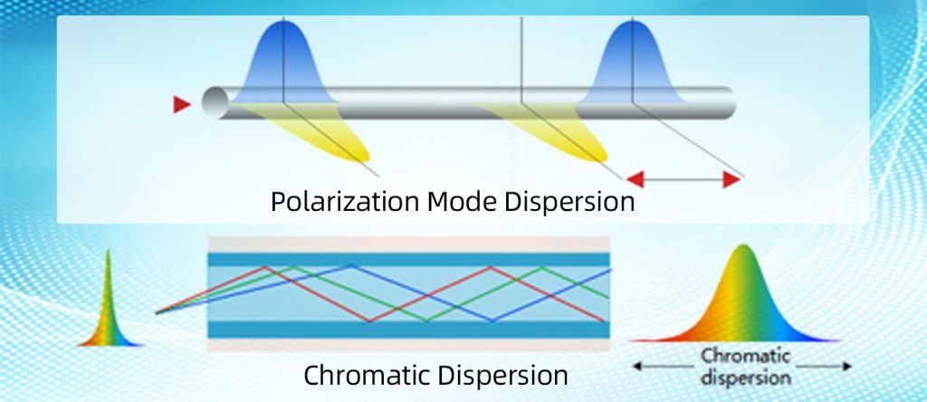
● Polarization Mode Dispersion (PMD)
A special type of dispersion related to polarization. Due to small imperfections in the fiber (such as core ellipticity, uneven stress), the two orthogonal polarization components of light (e.g., horizontal and vertical) travel at different speeds. Even at the same wavelength, pulses can broaden due to this polarization-induced time delay.
2. Polarization
Light, as a transverse electromagnetic wave, has an electric field oscillating perpendicular to the direction of propagation. Polarization describes the orientation of this oscillation. Common polarization states include:
● Linear polarization – electric field oscillates along a fixed direction (e.g., horizontal or vertical polarization).
● Circular polarization – electric field direction rotates while amplitude remains constant.
● Elliptical polarization – electric field direction rotates with changing amplitude.
In optical fibers, polarization state changes can occur due to manufacturing imperfections (e.g., core ellipticity) or external stress (e.g., bending, compression). These changes mainly affect:
● Polarization-Dependent Loss (PDL) – Different polarization states experience different attenuation in optical components (e.g., filters, couplers), causing signal power fluctuations.
● Polarization Mode Dispersion (PMD) – As described above, orthogonal polarization components travel at different speeds, causing pulse broadening, especially significant at high data rates.
Why Dispersion and Polarization Must Be Considered in Optical Transceivers
The core of optical communication is transmitting digital signals (“0” and “1”) via optical pulses. Dispersion and polarization directly degrade pulse integrity, reducing transmission quality or even causing link failure.
1.Signal distortion caused by dispersion
Dispersion broadens pulses. At higher bit rates (e.g., ≥ 10 Gbps) or longer distances (e.g., > 10 km), neighboring pulses can overlap (inter-symbol interference) so that the receiver cannot reliably distinguish them, causing a high bit error rate.
Example: In single-mode fiber at 1550 nm, dispersion is ~17 ps/(nm·km). If the laser linewidth is 1 nm, over 100 km the dispersion-induced broadening is 1700 ps—far exceeding the 100 ps pulse period of a 10 Gbps signal, making communication impossible.
2.Signal instability caused by polarization
PDL – Can cause power fluctuations of 1–3 dB depending on polarization state, which over long distances may drop signal power below the receiver sensitivity threshold.
PMD – At high speeds (e.g., ≥ 40 Gbps), even short links (~50 km) can suffer significant broadening (> 50 ps). Combined with dispersion, this further degrades signal quality.
Mitigation of Dispersion and Polarization in Transceiver Design and Application
A. Design-Phase Optimization
1.For dispersion:
● Laser source selection: Use narrow-linewidth lasers (< 0.1 nm) to reduce material dispersion (fewer wavelength components → less broadening). For long-reach applications, prefer external modulation lasers (EMLs) over directly modulated lasers (DMLs) to avoid chirp-induced dispersion.
● Integrated dispersion compensation: Incorporate dispersion compensating elements (e.g., chirped fiber Bragg gratings (CFG), dispersion compensating fiber (DCF)) to offset accumulated dispersion. For example, a 100 Gbps long-haul module may include a CFG providing −1000 ps/nm compensation.
● Fiber type matching: For short distances (< 300 m) with multimode fiber (OM3/OM4), optimize the graded-index profile to reduce modal dispersion. For long distances, use single-mode fiber (SMF) and select dispersion-shifted fiber (DSF) or non-zero dispersion-shifted fiber (NZ-DSF) based on the operating wavelength to balance dispersion and nonlinear effects.
2.For polarization:
● Low-PDL component selection: Choose polarization-insensitive optics (e.g., lenses, filters, isolators) with PDL < 0.5 dB.
● PMD compensation: For high-speed modules (≥ 100 Gbps), integrate adaptive PMD compensation circuits to monitor and correct time delay between polarization components, keeping PMD broadening < 10% of the pulse period (e.g., < 25 ps for 40 Gbps).
● Polarization diversity reception: In the receiver, use dual-polarization detectors (e.g., for PDM-QPSK) to capture both orthogonal polarization components and avoid loss of signal due to polarization mismatch.
B. Application-Phase Best Practices
1.Link planning:
● For short distances (e.g., < 100 m within data centers), use multimode fiber but respect bandwidth limits (OM4 supports 100 Gbps up to ~150 m; longer requires SMF). For long distances (> 10 km), use SMF and pre-calculate total dispersion to deploy compensation modules (e.g., add DCF every ~100 km).
● Avoid excessive fiber bending or compression (bend radius < 30 mm increases stress and PMD). Ensure proper fiber routing and strain relief.
2.Monitoring and maintenance:
● Periodically measure link dispersion (using OTDR or dispersion analyzer) and PMD (using PMD tester). Keep total dispersion < 1600 ps/nm for 10 Gbps links and PMD < 0.5 ps/√km for 40 Gbps.
● For very high-speed (e.g., 400 Gbps) or ultra-long-haul (> 800 km) systems, use coherent optical communication with DSP-based real-time dispersion and PMD compensation—currently the mainstream for long-distance transmission.
Conclusion
Dispersion and polarization are unavoidable physical phenomena in optical communications. Their main impact is to degrade pulse integrity, limiting transmission speed and distance. Effective transceiver design uses component optimization and compensation techniques, while application-level planning selects appropriate fiber types and maintains link parameters, ensuring stable, high-speed optical communication.