GIGALIGHT Granted a Patent for External Light Source Optical Module
April 20, 2026, Shenzhen, China. – It was learned today from the intellectual property authority that GIGALIGHT has been granted a utility model patent for an 800G/1.6T/3.2T pluggable silicon photonics optical module with an external light source, which was filed in May 2025. The corresponding invention patent is currently under substantive examination.
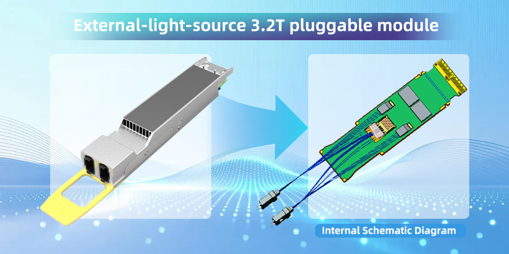

The main difference between pluggable external light source optical modules and conventional pluggable optical modules lies in the externalization of the light source. These modules adopt ELSFP or OSFP packaging. In terms of using an external light source, they share a similar concept with NPO/CPO solutions. Pluggable external light source optical modules are designed to address the following key challenges:
1. Thermal and Power Consumption Issues in High-Speed Modules
Conventional 1.6T/3.2T pluggable optical modules generate excessive heat due to high power consumption, which in turn affects the laser source, reducing its efficiency and causing operational instability. We believe that in the 1.6T/3.2T era, the stable operation and lifespan of lasers are critical considerations. Pluggable external light source optical modules effectively avoid the instability caused by high temperature and high energy consumption affecting the laser.
2. Continuation of Pluggable Module Evolution Path
Pluggable external light source optical modules can continue the long-term evolutionary path of pluggable optics. A key assumption is that if NPO/CPO optical interconnect solutions do not meet expectations, pluggable modules with external light sources will remain a viable and user-friendly alternative. In addition, such modules can support applications in immersion liquid cooling environments.
We believe that NPO/CPO solutions based on external light sources represent the optimal evolutionary path for next-generation optical interconnects. At the same time, if customers develop 1.6T/3.2T systems based on the pluggable external light source optical module described in this patent, it can significantly improve development efficiency—though at the cost of reduced port density.
About GIGALIGHT
As an open optical networking explorer, GIGALIGHT integrates the design, manufacturing, and sales of both active and passive optical devices and subsystems. The company’s product portfolio includes III-V optical modules, silicon photonics modules and silicon-based NPO/CPO engines, liquid-cooled optical modules, passive optical components, Active Optical Cables (AOCs), Direct Attach Cables (DACs), coherent optical communication modules, OPEN DCI BOX subsystems based on coherent and O-band DWDM optical modules, and UHD SDI video optical transceivers. GIGALIGHT focuses on applications including AI data centers, 5G transport networks, metropolitan WDM transmission, and ultra-HD broadcast and video, positioning itself as an innovative designer of high-speed optical interconnect hardware solutions.